Wiring a Water Well Pump Controller and Switch
To wire up a pump in a water well is a relatively small project you can do yourself (assuming you are the homeowner and local codes allow for this). Many well drillers are not licensed and finding a licensed electrician can add unnecessary time and costs to the job. Here is a list of things you will need.
Step 1: Basic Information and Getting Started
Before discussing the wiring, you might want to read up about pump fundamentals from Gould. The Gould company also offers an installation guide if you have not completed the pump installation. Gould pumps has been manufactured since 1848 and is a trusted brand that we recommend.
Before you get started on the wiring you should see the wiring diagram and guide from PumpWorld where you can also select and order your pump on-line. You might also want to read articles from PumpsOnLine.
You should also note that there are magazine devoted specifically to well, such as the Well Water Journal from the National Ground Water Association. Be sure to check your local building code such as those from Oregon and New Hampshire.
We recommend that you check with a licensed or factory service technician to review the horsepower, voltage rating and full load amperage for your pump. All electrical work must comply with national and local codes and regulations.
Step 2: Mount the Controller Box
The controller box needs to be mounted, typically near the pressure tank. The box is screwed to the wall as a surface mount. Choose an interior location, away from sunlight and not in a damp place, such as a well pit.
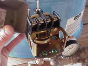
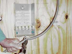
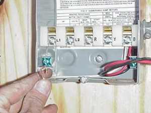
Step 3: Power to Pressure Switch
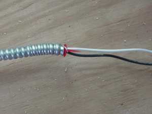
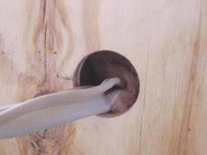
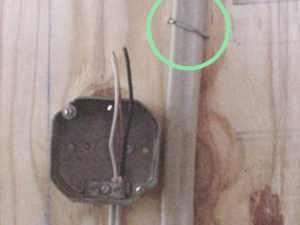
You will need to run power from the breaker box to the pressure switch. Here we are using two-wire, plus ground. The switch is feed from the left and a three-wire cable leads to the controller box. Because this application is situated in a barn area, we have chosen to use BX rather than Romex cable. Add the appropriate connectors for BX or Romex to the switch. Cut and strip the leads and attach to the switch. (Note that rodents can easily chew through the white plastic, so we have used BX in this installation.) Be sure to check with local building codes in deciding between type of cable and possible need for conduit. And don't forget - Be sure the power is OFF!
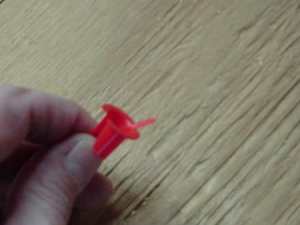
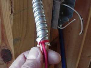
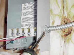
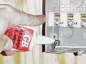
Step 4: Pressure Switch to Pump Controller
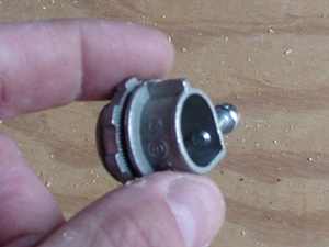
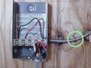
You will need to run power from the pressure switch on the pressure tank to the controller. This contains the starting relay and capacitors. This needs to be a three-wire, plus ground cable. First, cut the cable to length. Install the anti-short or insulated bushing to wrap the ground around the cable and install a connector clamp on the box. Before you connect the wires, it is advisable to avoid corrosion by using an anti-oxidant on the wire including the ground wire. Attached the wires, as marked. In our installation this box is within sight of the breaker panel and there is no need for a separate disconnect switch.
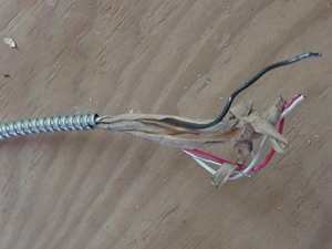
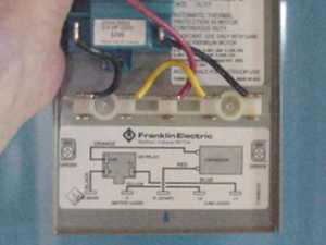
Step 5: Pump to Controller
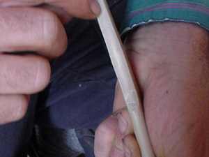
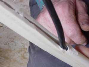
The cable from the pump typically has four strands and is cased in a heavy shielding. (Note that the conduit is not shown in this picture.) Typical wire strippers will not work and though not very elegant you can use a knife to carefully cut back and remove the shielding. You can then pull and expose the wire. Cable stapes for pump wire are much wider than normal staples. Attach the wires as per diagram, again using anti-oxidant. In this article we are focusing on the interior connection. If you need an exterior waterproof connection, click here.
Step 6: Problems and Trouble Shooting
Before you fire the pump up with the power, check out the Start-up Procedures Manual from the Submersible Water Pump Association. If you encounter problems, check the links below for help or e-mail us and we'll get an answer.
Trouble shooting chart from PumpWorld
Troubleshooting guide from PumpsOnLine
Pump Guide from Flotec Pump
Pump Handbook Series 2000 for troubleshooting and maintenance from the PumpZone